
High definition China High Strength 1X3 1X7 1X19 Hot Dipped Steel Core Guy Stay Stranded Wire
Every single member from our large efficiency profits team values customers’ requirements and organization communication for High definition China High Strength 1X3 1X7 1X19 Hot Dipped Steel Core Guy Stay Stranded Wire, We adhere towards the tenet of “Services of Standardization, to fulfill Customers’ Demands”.
Every single member from our large efficiency profits team values customers’ requirements and organization communication for China Galvanized Stay Wire, Gsw Wire, We have many years’ experience in hair product production, and our strict QC Team and skilled workers will ensure that we give you top hair products with the best hair quality and workmanship. You will get successful business if you choose to cooperate with such a professional manufacturer. Welcome your order cooperation!
Details
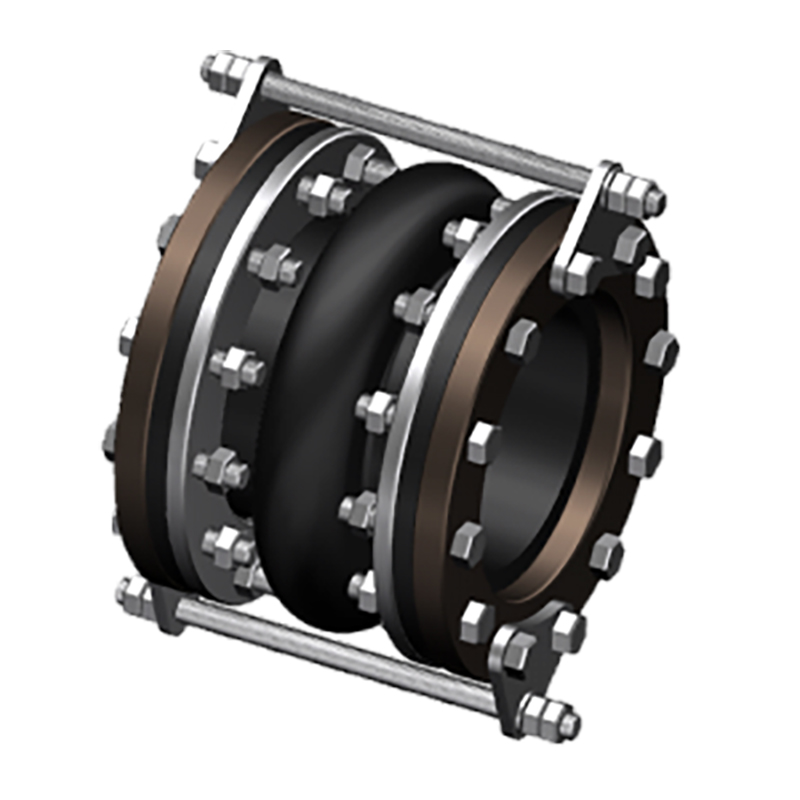
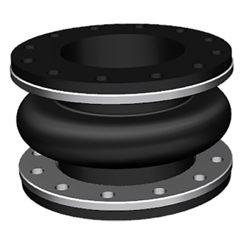
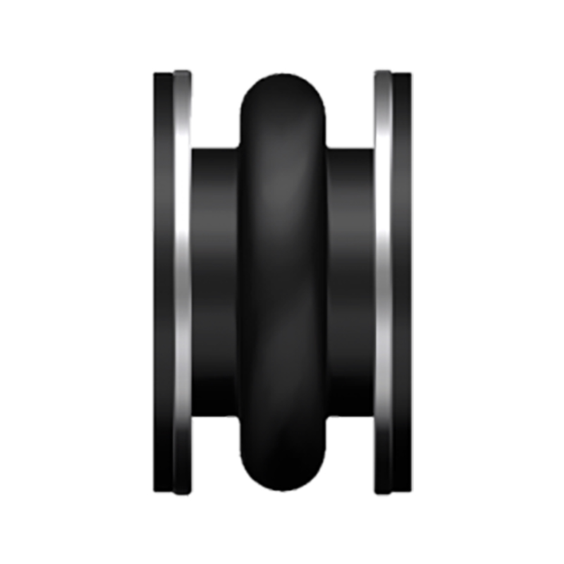
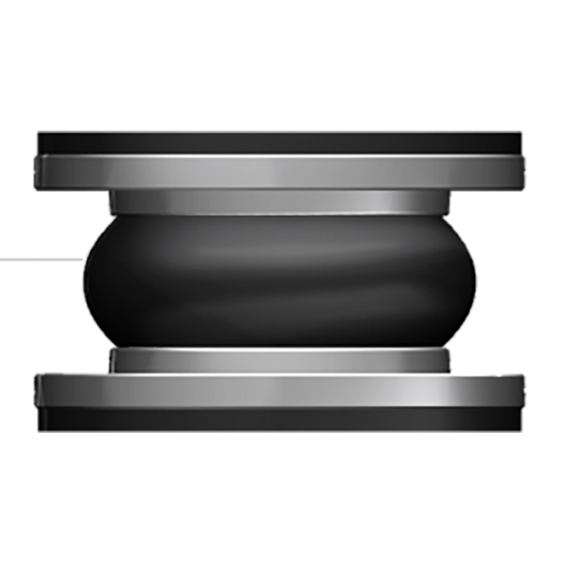
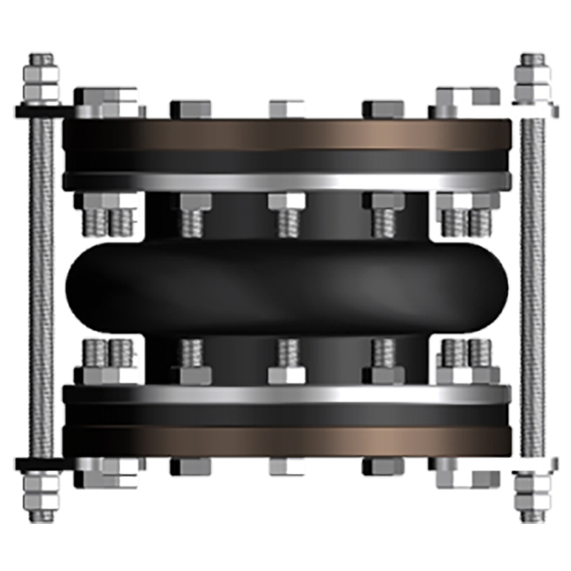
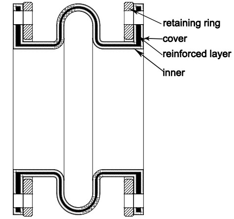
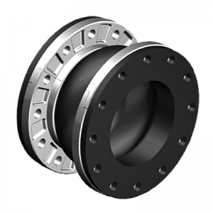
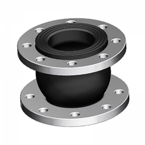
The spool type rubber joint is molded type, with a metal collar reinforced at the neck of the body. The ST stype uses a light reaining ring to support the integral flange. STF is filled arch, with 50% of the ST allowed movements, but it has 4 times spring rates than hollow arch.
| Specifications | I | II | III |
| Working Pressure Mpa (Kgf/Cm2) | 1Mpa (10) | 1.6 (16) | 2.5 (25) |
| Test Pressure | 1.5Mpa | 2.4Mpa | 3.75Mpa |
| Burst Pressure Mpa (Kgf/Cm2) | 3 (30) | 4.8 (48) | 5.5 (55) |
| Vacuum Kpa (Kgf/Cm2) | 53 (400) | 86(660) | 100 (750) |
| Materials | EPDM/NBR/SBR/NR | ||
| Diameter Range | DN15-DN600 (1/2″-24″) | ||
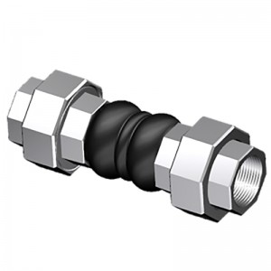
| Connection Method | FLANGETHREADCLAMP | ||
| Flanges Dimensions | DIN, EN,ANSI, BS, JIS and other standards | ||
| Applicable Medium | Air, compressed air, water, seawater, hot water, oil, acid, alkali etc. | ||
| Loading Port: | Qingdao, China | ||
| Shipment Terms: | FOB, CFR, CIF | ||
| Production Capacity: | 50000 set | ||
| Payment Terms: | L/C, T/T, D/P | ||
| Connection: | Flange, Thread | ||
| Flange Material: | Carbon Steel, Stainless Steel | ||
| Period of Delivery | about 21 working days | ||
|
SPOOL TYPE (ST) -American Standard ST |
||||||||||
|
Dimensions |
Movement Distance |
Operating Condition |
||||||||
|
Pipe Size |
O’all Length |
Flange OD |
Retaining Ring Thickness |
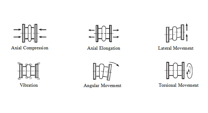
Axial Compression |
Axial Extension |
Lateral Deflection |
Angular Deflection |
Max w.p. (psi)-3,-4 |
Max Vacuum (in. of Hg)-5 |
|
|
Inch |
mm |
Inch |
Inch |
Inch |
Inch |
Inch |
Inch |
|||
|
2″ |
50 |
6″ |
6″ |
3/8″ |
7/16″ |
1/4″ |
±1/2″ |
19° |
150 |
26 |
|
2 1/2″ |
65 |
6″ |
7″ |
3/8″ |
7/16″ |
1/4″ |
±1/2″ |
15° |
150 |
26 |
|
3″ |
80 |
6″ |
7 1/2″ |
3/8″ |
7/16″ |
1/4″ |
±1/2″ |
13° |
150 |
26 |
|
4″ |
100 |
6″ |
9″ |
3/8″ |
7/16″ |
1/4″ |
±1/2″ |
10° |
150 |
26 |
|
5″ |
125 |
6″ |
10″ |
3/8″ |
7/16″ |
1/4″ |
±1/2″ |
8° |
150 |
26 |
|
6″ |
150 |
6″ |
11″ |
3/8″ |
7/16″ |
1/4″ |
±1/2″ |
6° |
150 |
26 |
|
8″ |
200 |
6″ |
13 1/2″ |
3/8″ |
11/16″ |
3/8″ |
±1/2″ |
6° |
150 |
26 |
|
10″ |
250 |
8″ |
16″ |
3/8″ |
11/16″ |
3/8″ |
±1/2″ |
5° |
150 |
26 |
|
12″ |
300 |
8″ |
19″ |
3/8″ |
11/16″ |
3/8″ |
±1/2″ |
5° |
150 |
26 |
|
14″ |
350 |
8″ |
21″ |
3/8″ |
11/16″ |
3/8″ |
±1/2″ |
4° |
150 |
15 |
|
16″ |
400 |
8″ |
23 1/2″ |
3/8″ |
11/16″ |
3/8″ |
±1/2″ |
4° |
150 |
15 |
|
18″ |
450 |
8″ |
25″ |
3/8″ |
11/16″ |
3/8″ |
±1/2″ |
3° |
150 |
15 |
|
20″ |
500 |
8″ |
27 1/2″ |
3/8″ |
13/16″ |
7/16″ |
±1/2″ |
3° |
150 |
15 |
|
24″ |
600 |
10″ |
32″ |
3/8″ |
13/16″ |
7/16″ |
±1/2″ |
3° |
150 |
15 |
|
SPOOL TYPE: FILLED ARCH (STF) -American Standard STF |
||||||||||
|
Dimensions |
Movement Distance |
Operating Condition |
||||||||
|
Pipe Size |
O’all Length |
Flange OD |
Retaining Ring Thickness |
Axial Compression |
Axial Extension |
Lateral Deflection |
Angular Deflection |
Max w.p. (psi)-3,-4 |
Max Vacuum (in. of Hg)-5 |
|
|
Inch |
mm |
Inch |
Inch |
Inch |
Inch |
Inch |
Inch |
|||
|
2″ |
50 |
6″ |
6″ |
3/8″ |
7/32″ |
1/8″ |
±1/4″ |
9.5° |
150 |
26 |
|
2 1/2″ |
65 |
6″ |
7″ |
3/8″ |
7/32″ |
1/8″ |
±1/4″ |
7.5° |
150 |
26 |
|
3″ |
80 |
6″ |
7 1/2″ |
3/8″ |
7/32″ |
1/8″ |
±1/4″ |
6.5° |
150 |
26 |
|
4″ |
100 |
6″ |
9″ |
3/8″ |
7/32″ |
1/8″ |
±1/4″ |
5° |
150 |
26 |
|
5″ |
125 |
6″ |
10″ |
3/8″ |
7/32″ |
1/8″ |
±1/4″ |
4° |
150 |
26 |
|
6″ |
150 |
6″ |
11″ |
3/8″ |
7/32″ |
1/8″ |
±1/4″ |
3° |
150 |
26 |
|
8″ |
200 |
6″ |
13 1/2″ |
3/8″ |
11/32″ |
3/16″ |
±1/4″ |
3° |
150 |
26 |
|
10″ |
250 |
8″ |
16″ |
3/8″ |
11/32″ |
3/16″ |
±1/4″ |
2.5° |
150 |
26 |
|
12″ |
300 |
8″ |
19″ |
3/8″ |
11/32″ |
3/16″ |
±1/4″ |
2.5° |
150 |
26 |
|
14″ |
350 |
8″ |
21″ |
3/8″ |
11/32″ |
3/16″ |
±1/4″ |
2° |
150 |
15 |
|
16″ |
400 |
8″ |
23 1/2″ |
3/8″ |
11/32″ |
3/16″ |
±1/4″ |
2° |
150 |
15 |
|
18″ |
450 |
8″ |
25″ |
3/8″ |
11/32″ |
3/16″ |
±1/4″ |
1.5° |
150 |
15 |
|
20″ |
500 |
8″ |
27 1/2″ |
3/8″ |
13/32″ |
7/32″ |
±1/4″ |
1.5° |
150 |
15 |
|
24″ |
600 |
10″ |
32″ |
3/8″ |
13/32″ |
7/32″ |
±1/4″ |
1.5° |
150 |
15 |
Products categories
-
Best Price for China Neoprene Wraps Strap Ankle...
-
Hot Sale for China Threaded Rubber Expansion Jo...
-

Reasonable price China CNC Machining/Machined P...
-
OEM Factory for China Car Steel Rubber Ball Joi...
-
Factory supplied China Forged Wn Welding Neck 1...
-
Price Sheet for China Metal Expansion Pipe Coup...
-

Phone
-

E-mail
-

Whatsapp
whatsapp

-

WeChat
Jessy Lin

-
WeChat
Ellen Zhang


